Most calibrations start from an assumption: your UV source lights the whole frame evenly, so one curve covers the entire print. That's true in the majority of cases, and it's Calibration Flow's default.
But the assumption breaks the moment exposure stops being uniform. A UV LED whose intensity drops at the edges, a contact frame that clamps tighter in the center than in the corners, a sun exposure with an angle-of-incidence gradient. In those cases the top of your print and the bottom don't receive the same dose, so they don't call for the same correction. Multi-zone correction exists for exactly this problem.
#What you do
In the transform step, you choose a zone mode: a single zone (default), two zones, or four.
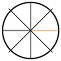
In two zones, the image is cut horizontally in two. You see two dropdowns: TOP (blue arrow) and BOTTOM (orange arrow). Each one lets you pick a curve from your library, or the standard curve. You assign a curve to each half.
In four zones, the image is split into quadrants — TOP LEFT, TOP RIGHT, BOTTOM LEFT, BOTTOM RIGHT — laid out in a 2×2 grid. Four dropdowns, one curve per quadrant.
<!-- src: index.html:4289-4481 — selects step3CurveTop/Bottom (2z) + step3CurveTL/TR/BL/BR (4z) -->When you generate, the app applies each zone's own correction table, then recombines the pieces into a single image. So you can check the assembly, it draws an orange separator line between the zones and writes the name of the curve used in each zone directly onto the control print. If you enabled the control strip, it's drawn in each zone with that zone's curve, not a global strip.
<!-- src: config.js:7918 orange line rgba(255,107,53,.7) ; config.js:7927/8041 per-zone drawZoneLabel ; cf-control-strip drawInZone -->#Why it's valuable
For a UV source that doesn't light flat. This is the tool's reason to exist. You measure a target at the top of the frame, another at the bottom, and you find the densities don't build the same way. Instead of averaging the two into a curve that's mediocre everywhere, you calibrate each region and correct it with its own response. The final print is uniform even though your exposure wasn't.
For large format. The larger the surface, the more visible a light falloff at the edges becomes. On an A3+, the gap between center and corners can be enough to plug the shadows on one side. Four quadrants give you a correction net where a single curve would leave a diagonal drift.
For diagnosing before correcting. Even if you end up staying in one zone, printing two targets (top and bottom) and comparing their curves tells you whether your hardware exposes evenly. It's a test of your setup as much as a generation option.
#When you don't need it
When your exposure is uniform. If your source lights flat — and a Luminograph on a matched format is built for that — a single curve is the right choice. Splitting a uniform exposure into zones only introduces correction breaks at the boundary between two regions. You're chasing noise that isn't there.
For arbitrary local correction. Zones are rectangular cuts, two halves or four quadrants, nothing else. If you want to lighten a free-form area in the middle of the image, this isn't the tool — that's a mask in Photoshop. Calibration Flow doesn't do arbitrary-shape masking.
Until you've measured each zone. Assigning different curves without having measured them separately is inventing a correction. Each zone needs its own printed and scanned target. Multi-zone doubles or quadruples your measurement work — only go there if the non-uniformity is real and documented.
#Worth remembering
| Item | Value |
|---|---|
| Modes | 1 zone (default), 2 zones (top/bottom), 4 zones (quadrants) |
| Split | Horizontal (2 zones) or 2×2 grid (4 zones) |
| Assignment | One dropdown per zone → a curve from your library |
| Visual cue | Orange separator line between zones |
| Label | Curve name written into each zone on the print |
| Control strip | Drawn per zone, with that zone's curve |
| Measurement required | One printed and measured target per zone |
#The test
Print two targets, one placed at the top of your frame, the other at the bottom, on the same exposure. Measure them separately in Calibration Flow, save both curves. Switch to 2-zone mode, assign the "top" curve to TOP and the "bottom" curve to BOTTOM. Generate. Look at the separator line: if the two curves are nearly identical, your exposure is uniform and you can go back to one zone with peace of mind. If they diverge clearly, you've just measured your source's non-uniformity — and corrected it.